 1 / 13
Inline Rotational Viscometer
Model: JS-ND
Compared with solid-state types, the inline rotational viscometer is more flexible and more compact, retaining the accuracy and continuity of viscosity measurement while adding greater installation flexibility.
Product Features
- The inline rotational viscometer features an integrated maintenance-free design
- the probe has no moving parts and supports long-term online measurement. Combined with a transmitter, the viscosity signal can be output via a standard 4-20mA signal or 485 communication, with real-time display and data transmission. It can be mounted on reactors, reaction tanks and pipelines for flexible, convenient installation.
Application Scenarios
- Suitable for inline measurement in reactors, reaction tanks and pipelines
- widely used for process control and monitoring of batch polymerization, emulsification and dispersion in the chemical, petroleum, coatings and adhesives industries.
Technical parameters
| Product Name | Inline Rotational Viscometer |
|---|---|
| Product Model | JS-ND rotational viscometer |
| System Composition | Probe + transmitter |
| Design Features | Integrated maintenance-free design, no moving parts |
| Measuring Principle | Rotational torque principle viscometry |
| Applicable Scenarios | Reactor kettle, reaction tank, pipeline installation |
| Viscosity Measuring Range | 1-600000 mPa·s |
| Accuracy Class | 0.5% / 0.1% |
| Power Supply | 24VDC / 12V / 5V |
| Output Signal | 4–20 mA / RS-485 communication / 0–5 V |
| Temperature Range | ≤450℃ |
| Pressure Range | ≤6 MPa (50 MPa available on request) |
| Instrument Material | 304/316L/2205 stainless steel, titanium, HC alloy, etc. |
| Wetted Material | PTFE, 316L |
| Protection Rating | IP67 |
| Explosion-proof Rating | Exd II CT6 GB / ATEX / dust explosion protection Zone 22 |
| Connection Type | Flange, clamp, or threaded installation |
| Communication Interface | RS485, RS232 |
| Maximum Drive Temperature | ≤190 ℃ (recommended <170 ℃) |
| Display Configuration | 7" touch LCD / 11-inch touchscreen |
| Temperature Display | Yes |
| On-site Calibration Software | Optional |
| Standard Liquid Calibration | Yes |
| Working Principle | Motor-driven flexible coupling drives the rotor; the cohesive force of the solution acts on the rotor to create resistance, which the sensor converts into an electrical signal |
| Sensor Construction | Fully sealed welded construction, mechanical parts completely sealed |
| Design Advantages | Integrated sensor design, easy installation |
| Temperature Monitoring | Dual monitoring of process and drive temperature with automatic over-temperature shutdown protection |
| Temperature Protection Recovery | System resumes operation automatically after temperature drops |
| Application Field 1 | Oilfield drilling, polymer-flooding oil recovery, refining industry |
| Application Field 2 | Resins, chemical fibers, road asphalt |
| Application Field 3 | Beverages, conveyed liquids, paints and coatings |
| Application Field 4 | Adhesive manufacturing, marine industry fuel control |
| Typical Applications | Adhesives, paints, batch polymerization, emulsification and dispersion, in-line pipeline mixing |
Product Manual
Catalog
System information
The rotary viscometer control system consists of a probe and a transmitter. The viscometer adopts an integrated maintenance-free design.
Do not open any part of the probe; the product's integrated design has no parts requiring maintenance. During transport, do not grip the probe to avoid damaging the probe's sensing elements.
Note: when placing the product, do not let the probe's sensing elements touch the ground under load.
Product introduction
The viscometer consists of a sensor probe and a transmitter, and can be installed on reaction kettles, reaction tanks, and pipelines to measure liquid viscosity.
The probe of the rotary viscometer measurement system can accurately measure viscosity, and the transmitter displays it promptly. The viscometer can measure the viscosity of various liquids online, such as glue, paint, batch polymerization processes, emulsification and dispersion, and in-line mixing in pipelines.
The viscometer measurement system is maintenance-free in process control applications. The probe has no moving parts. The measurement system uses the rotary torque principle: the motor drives the rotor to rotate, and when the rotor spins, an adhesive force between it and the liquid impedes its normal rotation, which is converted by the sensor's microcomputer into a standard 4-20mA signal or 485 communication. The value can be displayed on the transmitter while a 4-20mA signal is output directly into the customer's field system.
Product parameters
|
Viscosity range |
1-600000MPa.S |
|
Accuracy class |
0.5%~0.1% |
|
Power supply |
24VDC. 12V .5 v |
|
Output signal |
4-20mA, 485 communication (Modbus RTU), 0-5V |
|
Temperature range |
≤85℃ (high temperature customizable) |
|
Pressure range |
≤6MPa (high pressure customizable up to 50MPa) |
|
Instrument material |
304, 316L, 902L, 2205 stainless steel, titanium HC; other materials customizable |
|
Wetted material |
PTFE, 316L |
|
Protection class |
IP67 |
|
Explosion-proof rating |
Exd ii CT6 GB ATEX dust explosion-proof Zone 22 |
|
Connection method |
Flange mounting, clamp mounting, thread mounting |
|
RS485, RS232 communication module |
|
|
Optional functions |
2.4 / 7 inch touch LCD display |
|
Temperature display |
|
|
On-site calibration software |
|
|
Standard fluid |
|
Selection table |
|||
|
Main model |
JS-N |
Old-style viscometer |
|
|
JS-ND |
Rotary viscometer |
|
|
|
JS-ND-Z |
Vibrational viscometer |
|
|
|
JS-ND-HX |
Resonance viscometer |
|
|
|
-L |
-LM |
Unit: mPa·s |
-LM500: viscometer with a range of 500 mPa·s |
|
-LC |
Unit: cSt |
-LC500: viscometer with a range of 500 cSt |
|
|
-LS |
Unit: s |
-LS500: viscometer with a range of 500 s |
|
|
-LP |
Unit: cP |
-LP500: viscometer with a range of 500 cP |
|
|
-W |
-W |
Ambient |
|
|
-WG |
High temperature |
|
|
|
-WL |
Low temperature |
|
|
|
-Y |
-Y |
Normal pressure |
|
|
-YG |
High pressure |
|
|
|
-YL |
Low pressure |
|
|
|
-X |
-X7 |
7-inch touch screen |
|
|
-X11 |
11-inch touch screen |
|
|
|
-C |
-C |
Conventional material |
|
|
-CT |
Titanium alloy material |
|
|
|
-C4 |
304 material |
|
|
|
-C6 |
316 material |
|
|
|
-CH |
Hastelloy material |
|
|
|
-A |
-AF |
Flange mounting |
|
|
-AL |
Thread mounting |
|
|
|
-AK |
Clamp mounting |
|
|
|
-S |
-S4 |
4-20mA output |
|
Product installation
Note:
When removing the probe from the packaging box or during installation, never lift the probe's sensing element with your hand.
During packaging, unpacking, transport, installation, and disassembly, excessive external force applied to the probe's sensing element can bend the probe. Bending deformation can destroy the product completely.
Please keep the original packaging of the viscometer. To avoid damage during transport or storage, the probe must be placed in the original factory packaging.
During handling or transport, be sure to package the product properly so that the probe will not bend or be damaged.
Unpack the probe, transmitter, and cable from the packaging box.
Once again: when handling the probe, never hold the sensing element at the top of the probe.
Open the package and remove the foam to see the bottom foam layer; carefully take the probe out of the bottom foam layer.
After unpacking the product, if there is any obvious damage, please contact our company.
Dimensions
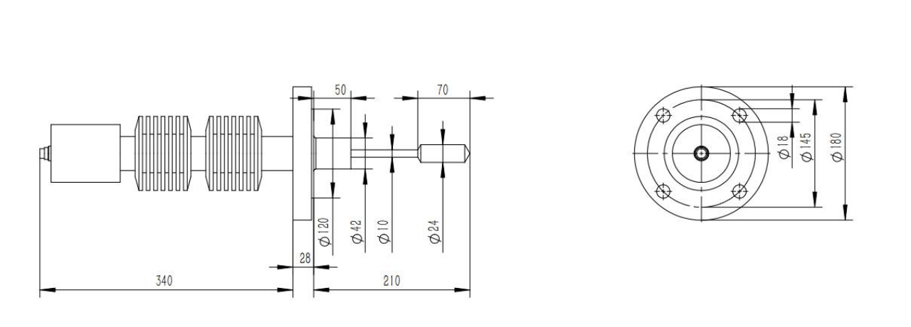
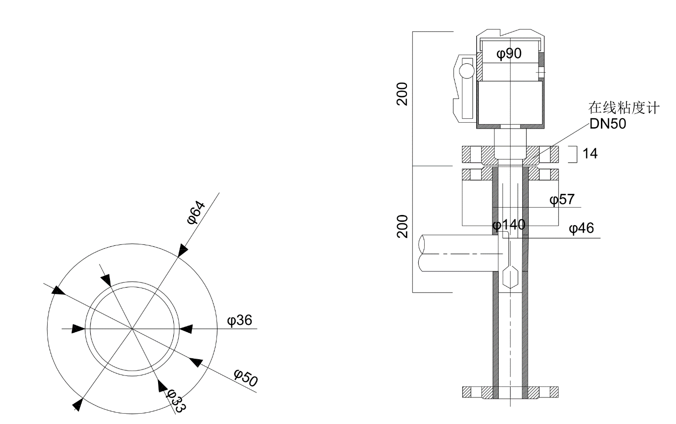
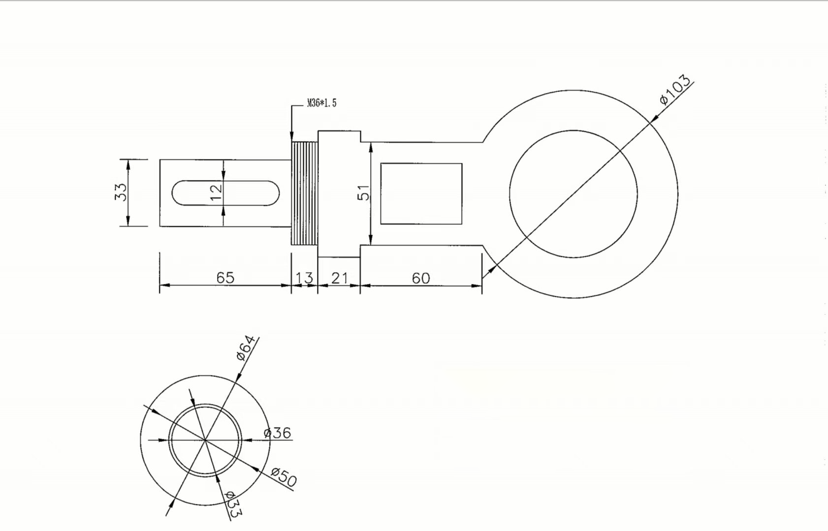
Mechanical installation
The sensor installation position needs to avoid stirring effects. Do not install the sensor probe too close to motors, agitators, water pumps, or other mechanical equipment that causes turbulence.
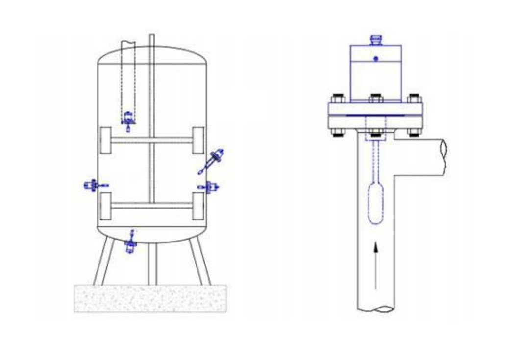
If the measurement results are not very stable, it indicates that the rotor size should be changed. The viscosity value can be adjusted via the rotor; the rotor viscosity range is calibrated at the factory.
The rotor size affects viscosity accuracy. The rotor is connected to the motor via a flexible or elastic connection to avoid the influence of liquid vibration on measurement accuracy during measurement.
In pipelines, using turbulence devices or shunting can reduce the impact on rotation, but do not install the probe where the flow velocity is unstable, because excessive fluid velocity affects measurement results.
As long as the process requirements of the control system are met, the probe can be installed in any position. During installation, the probe's sensing element must not be subjected to any external force, and the connection position must be mechanically stable.
If the measured material contains solid particles or substances that may hit the probe, a protective cover or other protective measures must be installed at the probe location. For details, please consult our company.
If the material has solidified on the probe, do not force-remove it; the rotor must be removed and cleaned with solvent or heated to melt.
Make sure the drive temperature is below the corresponding standard requirement:
|
Product model |
Maximum process temperature (℃) |
Remarks (custom range) |
|
O |
100 |
|
|
P |
200 |
|
|
Q |
300 |
|
|
R |
400 |
|
|
S |
Special cases |
|
|
T |
Ultra-high or ultra-low temperature |
|
To ensure system repeatability, the probe's sensing element must always be placed in the flow area of the liquid. In non-flow areas and where bubbles exist, the sensor probe will produce measurement errors due to fluid effects. If there are dead zones or blockages, an extended neck can be used to bypass the dead zone of the material.
The transmission cable must be placed in a wire duct for instrument or low-voltage cables, or routed in a separate conduit.
To prevent external interference with the measurement, please use shielded cables for the connecting cable.
Never route cables near high-voltage power lines.
If routed in a separate conduit, a hose connection is needed near the probe.
Electrical connection
I. Wiring diagram of the dual 4-20mA model:
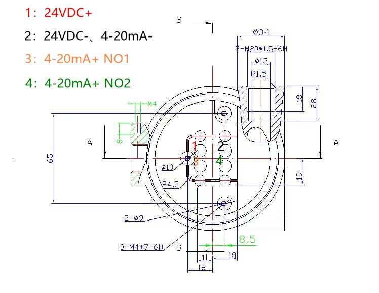
Wiring at the probe end. Open the round top cover, pass the transmission cable through the gland, connect the transmission wires according to the serial numbers; the wire colors can be used for identification.
II. Wiring diagram of the 4-20mA or 485 (choose one) model
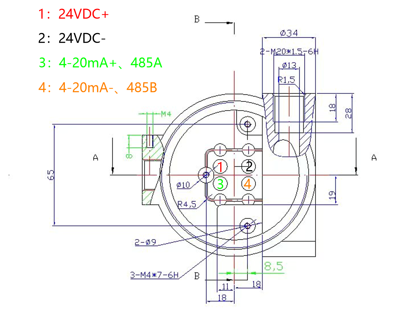
Do not loosen the internal connections of the wiring terminals.
After the wires are connected, close and lock the round top cover as it was. At the same time, tighten the cable-lock bolt to prevent water droplets from splashing in.
Precautions
Zeroing must be performed only after the probe is installed and the power and transmission cables are connected.
Make sure the probe is firmly installed; before zeroing, ensure the probe's sensing element can vibrate normally in air.
When the probe is wrapped with material, never perform zero adjustment.
If the probe needs to be removed or disassembled for system maintenance, it must be zeroed again after reinstallation.
To ensure good repeatability of the measurement system, zero-point adjustment must be performed under the same conditions.
Probe protection
For safety reasons, if the temperature exceeds the maximum value set by the range, the system will automatically shut down viscosity measurement. For some models, two temperature channels are monitored.
a) Process temperature:
If the process temperature exceeds the temperature specified for the sensor model, the viscosity measurement system shuts down automatically. When the process temperature drops back to the allowed temperature, the system resumes normal operation automatically.
Note:
If an error occurs, simply lower the process temperature to the temperature specified for the probe model; no other action is needed.
If the temperature frequently exceeds the value specified for the probe model, please contact our company to upgrade the probe model.
b) Drive temperature:
If the drive temperature is exceeded, the viscometer measurement system shuts down automatically. This parameter cannot be modified by the user. For details, please consult our company.
Generally, the drive temperature limit is 190℃. We recommend a drive temperature of 170℃ for all probe types. For drive safety, do not let the coil remain at high temperature for long periods; take cooling measures when necessary.
c) If the process temperature at the probe installation location exceeds 190℃, choose a high-temperature product, or use air cooling.
If the drive temperature exceeds the rated temperature for a long time, the probe may be permanently damaged. Please contact our company.
Working principle
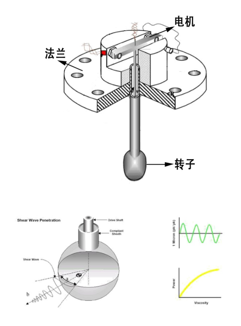
Rotary torque principle viscometry
1. The motor drive soft connection drives the rotor
2. The adhesive force of the solution acts on the rotor surface, producing a slight resistance
The sensor adopts a fully sealed welded construction; for the process, the drive mechanism is also fully sealed. The sensor's integrated design is easy to install.
Application cases
1. In oilfield drilling, detecting the viscosity changes of the mud carried by the drill bit makes it possible to analyze underground oil and gas changes.
2. In oilfield polymer flooding, detecting and controlling polymer viscosity can increase oil production.
3. In the refining industry, monitoring the viscosity of oil products is a key means of controlling oil quality.
4. In the resin and chemical fiber industries, viscosity control is the quality assurance of product forming.
5. In road asphalt paving, asphalt viscosity control is the guarantee of road quality.
6. In the beverage industry, controlling beverage viscosity guarantees the beverage's taste.
7. In the liquid transport industry, detecting viscosity to control the load of transport pumps can save a lot of energy.
8. In the coatings and paints industry, viscosity control is an important quality guarantee.
9. Viscosity control in the glue-making industry is a key technology for realizing automated production lines.
10. Viscosity control in ship industry fuel control plays an important role in environmental protection.
Note
Installation requirements:
Please follow the instructions below carefully
◆ When handling the probe, do not hold the sensing element at the top of the probe. Only hold the flange and rear cover parts.
◆ If necessary, connect the terminals of the probe and transmitter according to the numbers indicated on the lines. Do not loosen or damage the wires connected inside the probe.
◆ Only our company or the local authorized agent may calibrate or repair the components inside the probe.
◆ No part of the probe other than the rear cover should be opened. There are no parts inside the probe requiring adjustment; calibration and adjustment have been completed at the factory. When connecting the probe wires, make sure the transmitter's power is off.
◆ Do not use water to cool the drive inside the probe. Only clean, dry instrument air may be used for cooling.
◆ When the transmitter's rear cover is opened, the power section is exposed; be sure to disconnect the power.
◆ The standard power supply of the viscometer system transmitter is 24VDC;
◆ The system calibration already includes the length of the transmission cable; do not change the length arbitrarily, otherwise the measurement accuracy will be affected. If the system is equipped with a safety barrier, the calibration also includes the safety barrier; do not replace it arbitrarily.
◆ Please keep the original factory packaging. When storing or transferring the probe, use the original factory packaging to avoid damage.
◆ When zeroing, the probe must be clean and firmly installed in an empty pipe/tank, and able to rotate freely without obstruction in air.
◆ During normal production operation, zeroing must not be performed. If this happens, to ensure system repeatability, re-zero must be performed in air under the same conditions.
◆ If the system is not operated in a safe manner, the warranty is void. Obvious system damage, transport damage, and bent probes are not covered by the warranty!
◆ Before factory repair, the system should be thoroughly inspected by an authorized service technician.
◆ Please consult our company or the local authorized agent for further instructions and explanations.
Operating conditions
1. To ensure the repeatability of the equipment, the probe must be completely immersed in the liquid for measurement at all times.
2. The liquid at the probe location must remain flowing.
3. The probe should be installed in a place without bubbles and without fluid dead zones.
4. To maintain optimal reproducibility, the slurry flow rate should remain constant to prevent sediment formation.
5. The probe is best installed in the center of the fluid to prevent material sedimentation and coking on the probe. On certain special occasions, the probe needs regular cleaning.
6. Prevent solids in the fluid from hitting the probe. If you encounter this problem, please contact our company or the local authorized agent.
7. Prevent excessive agitation; a perforated round shield can be used for protection to reduce the impact of the liquid's violent surging.
8. For detecting small differences in the viscosity measured by the system, temperature compensation or moving averaging of the measurement data can be set as needed.
9. Do not exceed the maximum and minimum ranges specified by the system. In particular, do not exceed the specified temperature and pressure.
Document Download
在线旋转粘度计说明书(新).docx
Click to download document
Need more information?
For any product inquiries or technical questions, please feel free to contact us at any time.