
Servo Level Transmitter
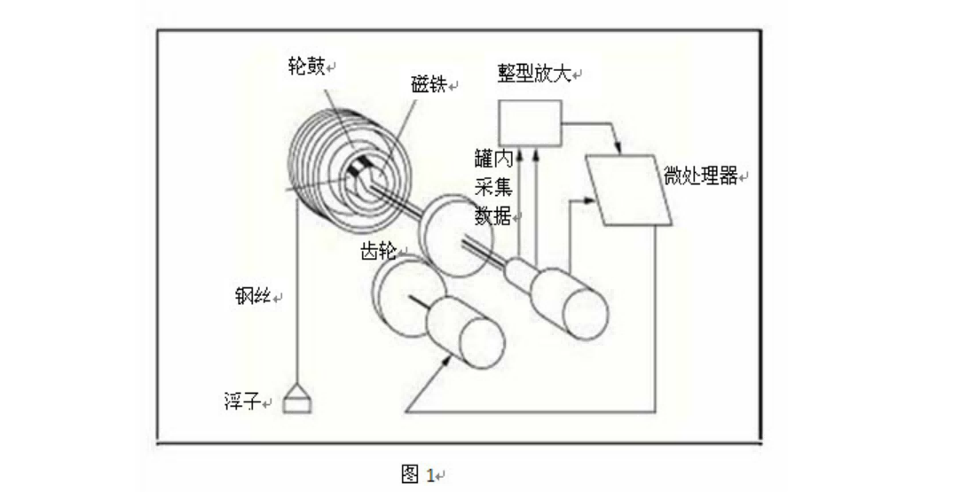
Based on the buoyancy-balance principle, a small float driven by a micro servo motor measures level and other parameters with high accuracy. As shown in Figure 1, the float is suspended inside the instrument housing by a measuring wire wound on a precision-machined outer drum; an outer magnet fixed inside the outer drum is coupled to an inner magnet fixed on the inner drum.
Product Features
- The servo level transmitter works on the buoyancy-balance principle, with a float driven by a micro servo motor. Accuracy reaches ±0.7mm, with temperature compensation
- the closed-loop feedback design ensures stable and reliable operation. Its all-stainless-steel housing is durable and corrosion-resistant.
Application Scenarios
- Suitable for level measurement in oil tanks, chemical storage tanks, wastewater treatment and food and beverage vessels.
Technical parameters
| Measuring Range | 0-32 m |
|---|---|
| Accuracy | ±1mm |
| Display resolution | 1mm |
| Ambient temperature | -40~+55℃ |
| Relative humidity | ≤95% |
| Output Signal | Analog 4-20 mA DC; digital HART 1200 baud frequency shift keying (FSK) |
| Supply voltage | 24V DC |
| Working pressure | <4.0MPa |
| Medium temperature | <200℃ |
| Material | Electronics chamber: cast aluminium; drum chamber: 316 stainless steel; wetted parts: 316L |
| Connection flange standard | HG20593-97 RF face DN=65mm PN=1.6MPa |
| Connection Thread | M20×1.5 (4-wire: two power, two current output) |
| Explosion-proof Rating | Exd IIC T6 |
| Protection Rating | IP67 |
| Associated equipment | a safety barrier is required for intrinsically safe applications |
Product Manual
Catalog
The servo level gauge is based on the principle of buoyancy balance: a micro servo motor drives a small displacer, allowing precise measurement of level and other parameters. As shown in Figure 1, the displacer is suspended inside the instrument housing by a measuring wire, and the wire is wound on a precisely machined outer drum; an outer magnet is fixed inside the outer drum and is magnetically coupled to an inner magnet fixed in the inner drum.
When the level gauge operates, the weight of the displacer acting on the thin wire produces a torque on the magnet of the outer drum, changing the magnetic flux. The flux change between the drum components alters the output voltage of the electromagnetic sensor (Hall element) on the inner magnet. This voltage is compared with a reference voltage stored in the CPU; when the displacer is balanced, the difference is zero. When the level of the measured medium changes, the buoyancy of the displacer changes, which changes the magnetic coupling torque and thus the output voltage of the temperature-compensated Hall element. The difference between this voltage and the CPU reference drives the servo motor to move the displacer up or down until balance is restored. The whole system forms a closed-loop feedback circuit (as shown in Figure 1) with an accuracy of up to 0.7 mm, and its built-in build-up compensation compensates for changes in wire tension caused by medium adhering to the wire or displacer.
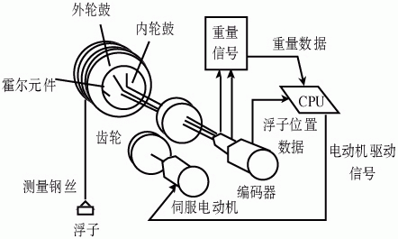
Figure 1 System composition of the level gauge
I. Working Principle:
Measurement of the JSUU-SF-001 servo level gauge is designed on the principle of buoyancy balance. Magnetic coupling is achieved between the inner magnet wheel fixed to the drive motor and the precisely machined drum (the outer magnet wheel), so that drum and drive motor rotate synchronously, while the inner magnet wheel and drum are completely isolated by the instrument housing, fully separating the measured liquid chamber from the electrical part and meeting explosion-proof requirements. The measuring wire is wound evenly and neatly on the drum. The displacer is lowered into the tank by the measuring wire. When the level (interface or density) in the tank changes, the displacer weight changes with the level, and this change creates a coupling difference between the drum and the inner magnet wheel. After the signal is processed by the microprocessor, a control command is sent to the servo motor so that the displacer always follows the level change. The level height is then obtained from the measured drum rotation angle by calculation. To measure interface or density, simply set it in the Chinese menu. Structure diagram (see Figure 1).
Main technical specifications:
Measuring range: 0-32 m
Accuracy: 1 mm
Display resolution: 1 mm
Ambient temperature: -40~+55
Relative humidity: 95%
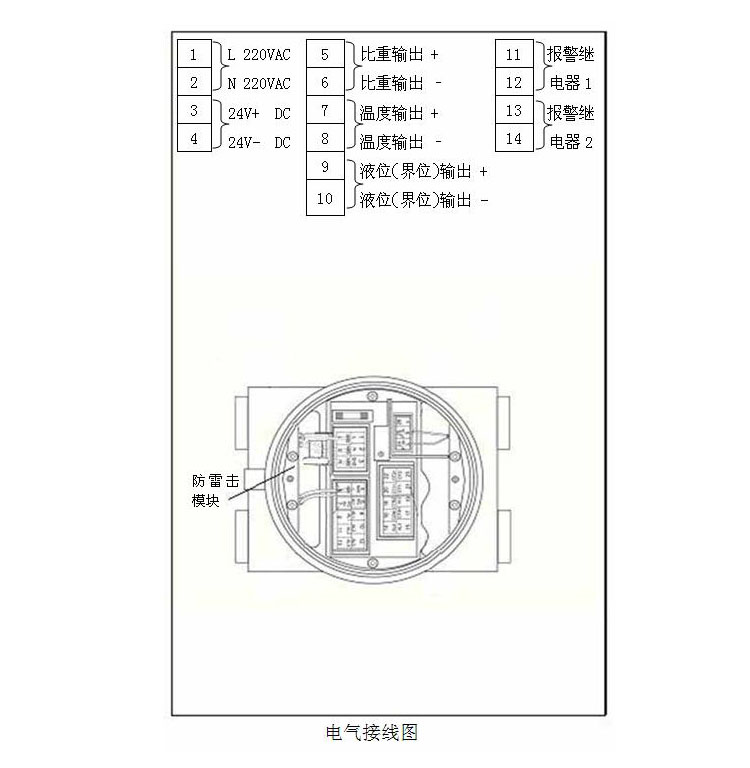
Four-wire system: two wires for power supply; thread M20 1.5
two wires for current output; thread M20 1.5
Output: analogue 4-20 mA DC
Digital HART 1200 baud frequency-shift keying (FSK)
Supply voltage: 24 V DC
Working pressure: < 4.0 MPa
Medium temperature: < 200℃
Material: electronic compartment: cast aluminium
drum chamber: 316 stainless steel (other materials available on request)
wetted material: 316L (selectable according to user requirements)
Connection flange standard: HG20593-97 RF face DN=65mm PN=1.6MPa
Explosion protection: Exd IIC T6
Protection rating: IP67
Associated equipment: a safety barrier is required for intrinsically safe applications
Features:
Level measurement accuracy 1 mm;
Simultaneous measurement of level, interface, density and tank temperature;
Adjustment without opening the cover;
Automatic calibration;
Local display and remote transmission;
Bubbles and emulsion layers on the liquid surface do not affect accuracy;
Sediment at the tank bottom does not affect accuracy;
Suitable for measurement in various tank types;
Simple parameter setting with a convenient Chinese menu and display;
Complete isolation between the liquid chamber and the electronic measuring chamber;
Automatic displacer weight compensation: the JSUU-SF-001 checks whether the displacer is fouled or corroded by comparing its weight in air with a preset displacer weight. Periodic weight checks can be configured; deviations are corrected and an alarm is given or logged. Automatic displacer weight compensation ensures instrument accuracy in high-precision applications.
Automatic wire length correction: when the displacer moves from the level to the reference point (the internal mechanical stop), the instrument automatically checks and corrects, and performs automatic calibration. This can be done manually or automatically at a preset interval. Automatic wire length calibration compensates changes in wire length caused by thermal expansion and contraction of metal due to tank temperature changes, thus ensuring measurement accuracy.
II. Installation:
III. Electrical connection:
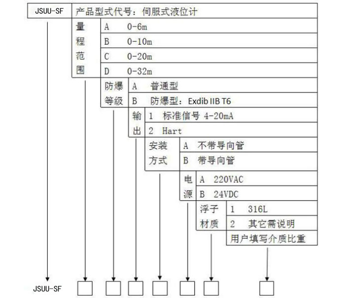
IV. Model selection table:
V. Extendable technologies from Jinglai Electronics:
1. Connection to a higher-level PLC control system for automatic control (mainly Mitsubishi, Siemens and Schneider PLCs).
2. Bluetooth phone display: level height shown on the phone (Bluetooth range 10 m).
3. Supports GPRS remote transmission and GSM remote communication.
4. Supports RS232 and RS485 communication (MODBUS protocol, etc.).
5. Supports DCS configuration display.
VI.Maintenance and Use
1. The switch is a fragile component; use a short length of stranded wire as a transition where it connects to the lead.
2. The switch must be used in a vertical position with contacts facing up; tilt angle must not exceed 30°.
3. In relatively humid environments, wrap the connection with insulating material.
4. When the guide tube is long, add a fixing measure at the lower end.
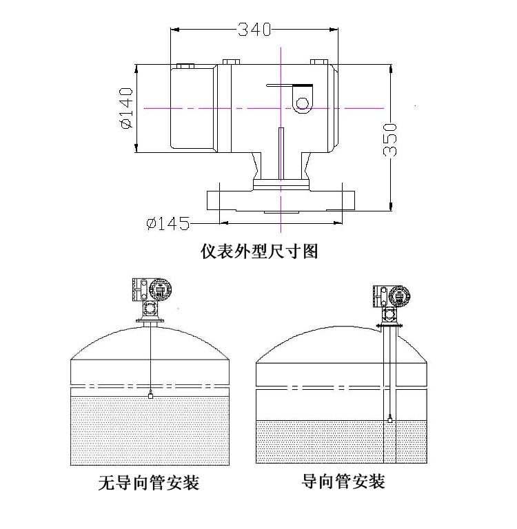
5. Installation depends on site conditions: open ponds usually use bracket mounting, while closed vessels use flange or external float-chamber mounting.
6. If the guide tube is too long during use, remove the terminal box, cut off the excess guide tube and refit the terminal box.
7. For outdoor use, fit a protective cover over the terminal box.
8. To improve transport efficiency and reduce cost, oversized units are best supplied in sections: mating threads are machined, the customer only needs to screw the sections together and perform a hydrostatic test to confirm no leakage before use.
VII. Ordering information:
1. Model and specification
2. Measuring range (centre distance L)
3. Working pressure
4. Working temperature
5. Material requirements
Document Download
伺服液位计新说明书
Click to download document
Need more information?
For any product inquiries or technical questions, please feel free to contact us at any time.