
Wing Icing Sensor
Based on fibre-optic icing sensor theory and weak-signal detection theory, the system is designed in detail across four areas: the detector (including the fibre-optic sensor), the signal-processing circuit, the host monitoring software and the communication protocol.
Product Features
- The wing icing sensor is designed specifically for aircraft, detecting changes in wing aerodynamic profile and surface icing in real time. Accurate and reliable, it provides important assurance for flight safety.
Application Scenarios
- Mainly used for wing ice detection on aircraft in conjunction with de-icing systems, and also suitable for ice monitoring on airport runways.
Technical parameters
| Detection parameters | Icing, ice thickness, standing water, temperature |
|---|---|
| Measuring Range | Ice 0-0.3mm, 0.3-50mm, 50-100mm |
| Resolution | 0.2mm |
| Detection Accuracy | 0.5mm |
| Supply voltage | 3.3V、5V、12V、24V DC |
| Power | <0.4W |
| Sensitivity | 0.4℃ |
| Communication Mode | 4-20mA、RS485 MODBUS |
| Temperature Output | -40℃~85℃ |
| Temperature Compensation Range | -40℃~85℃ |
| Probe Material | SUS304 / PTFE (Teflon) |
| Ambient temperature | -40℃~85℃ |
| Dimensions | Φ25×20mm, Φ32×20mm, Φ40×20mm (customizable on request) |
| Protection Rating | IP67 |
Product Manual
Catalog
1. Overview
Ice accretion on an aircraft airframe has a great effect on its aerodynamic shape and seriously affects flight safety. Wing icing in particular directly causes insufficient lift, so that the aircraft cannot take off, climb or even maintain flight. An aircraft flies mainly because the wing profile generates a pressure difference that provides lift; when the wing ices up, its aerodynamic shape changes and its surface finish is badly affected, so the airflow can no longer follow the expected path and lift is lost — the aircraft then loses the ability to keep flying. Insufficient lift prevents take-off and climb, and in flight the same condition causes a severe loss of lift, a rapid descent, a sharp loss of altitude and even a crash. De-icing of aircraft is therefore a very important task that must not be neglected.
Combining domestic research on actual wind conditions, the company has developed an aircraft wing icing detection system. The theory of rapid icing calculation, the theory of fibre-optic icing sensors and the theory of weak-signal detection are introduced first; on this basis the system is designed in detail in four areas: the detector (including the fibre-optic sensor), the signal processing circuit, the host monitoring software and the communication protocol. The detector and signal processing circuit convert the weak change of icing state at the sensor into a pronounced voltage signal at the acquisition end. The host software implements the serial communication module, the graphical data display module and the data storage module, processes the icing voltage signal sent by the hardware, provides a friendly human-machine interface showing the current icing alarm state, and saves the real-time data to a file. Signal processing for icing and analysis of rain interference were also completed for this system.
Field practice shows that the system is feasible for wing icing detection and can perform the icing alarm function while also using microwaves to shed the ice layer; the results are very satisfactory. Research and application in aircraft wing icing detection are still at an early stage. Applying existing icing state analysis methods together with new fibre-optic icing sensors enables wing icing to be detected and the icing state to be obtained promptly and accurately, so that icing warnings and detection can be carried out and the harm of icing to the aircraft eliminated — which is of great significance for preventing potential natural hazards to aircraft.
In China, research on and application of icing sensors are still at an early stage, especially in the field of aircraft wings. Icing detection devices already designed domestically mainly use the magnetostrictive principle and can only judge blade icing from the degree of icing on the sensor; their detection is strongly affected by electromagnetic interference.
Compared with China, work abroad started earlier and receives more attention: aircraft icing models are studied more thoroughly and wing icing detection technology is ahead of the domestic level. The relatively mature main icing detection methods are: electrical, mechanical, optical and waveguide methods.
II. Working Principle
This type of icing detection technology exploits the electrical properties of ice. The most common is the capacitive type, which uses the different permittivity of ice, water and air to determine whether ice, water or air lies between the electrodes, and can also estimate ice thickness from the measured capacitance. A typical capacitive icing sensor is the one developed by Innovative Dynamics (USA), which covers ice thickness ranges of 0.5-1.5 mm and 1.5-50 mm.
(1) Optical method
This type of icing detection technology exploits the reflection, absorption and scattering of light by ice; the fibre-optic icing sensor is the most typical optical sensor. A fibre-optic sensor injects light of a given wavelength into the ice layer through a transmitting fibre; after reflection and scattering in the ice, part of the light returns to the receiving fibre, and the ice thickness can be derived from the intensity received. As early as 2003 Greek scientists successfully developed the first fibre-optic icing sensor, and later the UK also developed a high-performance fibre-optic icing sensor able to detect ice as thin as 0.1 mm.
(2) Waveguide method
This type exploits the absorption and reflection of acoustic or other waves by ice. Types include surface acoustic wave, ultrasonic pulse-echo and microwave resonance. A microwave icing sensor has already been used successfully on the Cessna Crusader 303 air-refuelling aircraft and can detect ice up to 25 mm thick.
With the rapid global growth of aviation, flight safety has received wider attention. Yet wing icing detection, a key technology for safe aircraft operation, is still relatively underdeveloped in China. Research that starts from basic theory and technical methods and delivers both substantial theoretical and methodological content and a practically engineered system is therefore an urgent need for safeguarding flight safety in China.
On the basis of icing detection theory, a multi-sensor system built around fibre-optic icing sensors detects the icing light-intensity signal, which is conditioned by the electronic system; the data acquisition module handles communication between the lower-level controller and the host computer, and the icing alarm information is finally displayed in real time on the host interface, with the alarm output controlled through a relay output module. Laboratory icing and rain-interference tests provided the basis for setting the icing alarm and rain-interference criteria.
Research the key theories of aircraft wing icing detection, including the theory of rapid icing calculation, the theory of fibre-optic icing sensors and the theory of weak-signal detection.
The wing icing detection system applies icing state analysis methods and fibre-optic icing sensors to detect the wing icing state and obtain it promptly and accurately, so enabling icing warning and detection. The system mainly involves three theories: rapid icing calculation, fibre-optic icing sensors and weak-signal detection.
1. Rapid icing-calculation theory
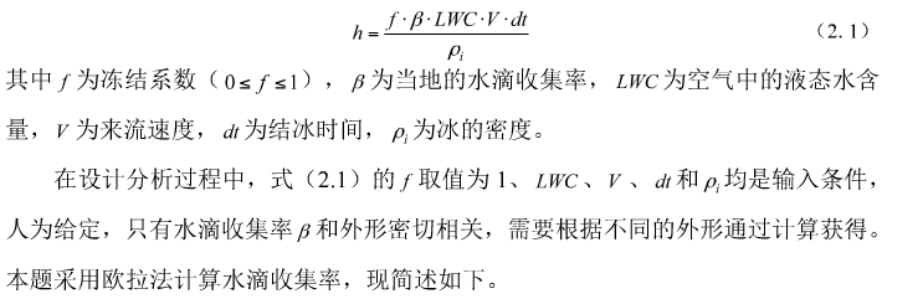
To establish the link between detector icing and wing icing, rapid calculation of both detector icing and wing icing is required; we use the following formula to calculate icing thickness:
2. Wall boundary condition: for water-drop phase calculation, unlike the airflow field, a wall-suction boundary condition should be adopted when computing the wall surface — if a water droplet collides with the surface, it is considered to flow out from the collision point.
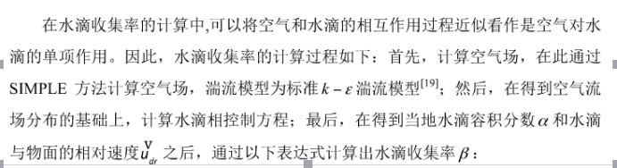
3. Calculation of water-drop collection rate
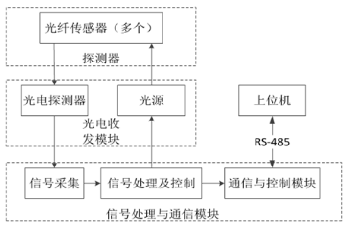
The system consists of four major parts: the detector (including the fiber-optic sensor), the photoelectric transceiver module, the signal processing and communication module, and the host computer. The three parts other than the host computer constitute the system hardware. The overall system block diagram is shown in Figure 3-1.
III. Signal Processing Circuit Design
The aircraft wing icing detection system comprehensively uses multiple fiber-optic icing sensors of different types to detect wing icing, display the current icing state in real time, and issue alarm signals. The hardware acquires and conditions the front-end sensor data and uploads it to the host computer for further processing. Since the wing icing detection system safeguards safe flight, the primary design concerns are stability and accuracy: the system must run stably without failures that interrupt operation, and must have high accuracy so that the alarm starts when the icing thickness at the detection point reaches 2mm; given the complex flight environment, the system also needs strong anti-interference capability.
The electronic system mainly includes 5 icing signal detection circuits and 1 power conversion circuit. Temperature detection, data acquisition, and 485-bus transmission are handled by the data module. Each icing signal detection circuit comprises a light-source emission circuit, a differential amplifier, a synchronous integrator, a correlator, and a low-pass filter. The square-wave signal generated by the square-wave generator in the light-source emission circuit serves on one hand as the switching signal of the switch circuit — amplified by the transistor to drive the infrared LED — and on the other hand as the reference signal of the synchronous integrator and the correlator; the differential amplifier takes the subtraction of the two received detector signals as its input, effectively reducing background-light influence; the synchronous integrator acts in the signal channel as an automatically frequency-tracking filter, removing part of the noise in the differential amplifier output; the correlator then applies cross-correlation, computing the cross-correlation between the periodic signal under test and a reference signal of the same frequency, so that the information carried by the periodic signal buried in noise can be detected. The temperature detector plays an auxiliary role in icing measurement: on one hand, under certain conditions, ice type is strongly related to temperature; on the other hand, the detection circuit only works and uploads data when temperature conditions are satisfied, and remains idle otherwise.
The development of the wing icing detection system includes detector (sensor) design, hardware design, and software design. In each part, the system's accuracy, reliability, and real-time performance were comprehensively considered.
IV. Parameters
Detection parameters: icing, icing thickness, standing water, temperature
Range: ice: 0-0.3, 0.3-50mm, 50-100mm
Resolution: 0.2mm
Detection accuracy: 0.5mm
Supply voltage: 3.3V, 5V, 12V, 24VD
Power: <0.4W
Sensitivity: 0.4℃
Communication: 4-20mA, RS485 MODBUS
Temperature output: -40℃~85℃
Temperature compensation range: -40℃~85℃
Probe material: SUS304 / PTFE (Teflon)
Ambient temperature: -40℃~85℃
Dimensions: 25*20mm, 32*20mm, 40*20mm (customizable on request)
Protection rating: IP67
V.Icing sensor series selection requirements;
|
No. |
Model |
Specification |
No. |
|
|
|
|
|
|
Item |
|||||
|
1. |
JS-J |
|
All-stainless-steel probe |
||||||||||||
|
2 |
Instrument type |
Ⅰ |
|
|
|
|
|
|
|
Remote transmission |
|||||
|
Ⅱ |
|
|
|
|
|
|
|
Wireless remote transmission |
|||||||
|
Ⅲ |
|
|
|
|
|
|
|
With microwave de-icing |
|||||||
|
3 |
Ambient temperature |
Ⅰ |
-40-40℃
|
||||||||||||
|
4 |
Remote transmission signal |
|
|
A |
|
|
|
|
|
Output 4~20mA DC, two-wire |
|||||
|
|
|
B |
|
|
|
|
|
Output 0~10mA DC, three-wire |
|||||||
|
|
|
C |
|
|
|
|
|
Output 0~4Ω |
|||||||
|
|
|
D |
|
|
|
|
|
HART protocol |
|||||||
|
|
|
E |
|
|
|
|
|
485 communication |
|||||||
|
5 |
Material |
|
|
|
Ⅰ |
|
|
|
|
Carbon steel |
|||||
|
|
|
|
Ⅱ |
|
|
|
|
Stainless steel |
|||||||
|
|
|
|
F |
|
|
|
|
PTFE (Teflon) |
|||||||
|
6 |
Measuring range |
|
|
|
|
L2 |
|
|
|
Range: 0~0.3mm |
|||||
|
|
|
|
|
L2.5 |
|
|
|
Range: 0.3~50mm |
|||||||
|
|
|
|
|
L4 |
|
|
|
Range: 50~100mm |
|||||||
|
|
|
|
|
L5 |
|
|
|
Range: custom size |
|||||||
|
7 |
Thread standard |
|
|
|
|
|
DN |
|
|
DN15mm |
|||||
|
|
|
|
|
|
DN |
|
|
DN20~32mm |
|||||||
|
8 |
Medium temperature |
|
|
|
|
|
|
T1 |
|
Normal: -5℃~40℃ |
|||||
|
|
|
|
|
|
|
T2 |
|
High: above 40℃ |
|||||||
|
|
|
|
|
|
|
T3 |
|
Low: below -5℃ |
|||||||
|
9 |
Other |
|
|
|
|
|
|
|
NV |
Supplied with WT-100 all-function remote-control digital display meter |
|||||
|
Selection example |
JS-J |
1Y |
2.5 |
A |
Ⅱ |
L4 |
D |
T25 |
NV |
JS-J wing icing detection system; ambient temperature; remote transmission signal; measuring range; thread standard; medium temperature |
|||||
VI. Runxinsen Electronics extendable technologies:
1. Connection to a higher-level PLC control system for automatic control (mainly Mitsubishi, Siemens and Schneider PLCs).
2. Bluetooth phone display: level height shown on the phone (Bluetooth range 10 m).
3. Supports GPRS remote transmission and GSM remote communication.
4. Supports RS232 and RS485 communication (MODBUS protocol, etc.).
5. Supports DCS configuration display.
VII. Detection performance
The parameters mainly measuring the detection performance of an icing sensor include resolution, sensitivity, temperature coefficient, accuracy, and precision.
Resolution is the minimum icing thickness an icing sensor can perceive.
Sensitivity is the ratio of the change in icing thickness to the change in the icing sensor's output.
The temperature coefficient is the ratio of the change in the icing sensor's output to the change in temperature when there is no icing signal.
Accuracy is the closeness of the center point of a series of data obtained by detecting the same icing thickness with the icing sensor to the actual icing thickness.
Precision is the degree of dispersion of the above series of data points relative to their center point.
VIII. Installation method
Install it where icing may endanger safety. The sensing membrane of the probe must be in contact with the medium to be detected so that the probe freezes at the same time as the medium; only then does detection work.
IX. Maintenance and use
The probe should not be covered or blocked by other objects; little maintenance is required — simply check periodically whether any object blocks the probe or whether dust has accumulated excessively and affects accuracy.
X. Ordering information:
1. Model and specification
2. Measurement site
3. Working pressure
4. Working temperature
5. Material requirements
6. Measurement accuracy
7. Output signal requirements
Document Download
机翼结冰传感器
Click to download document
Need more information?
For any product inquiries or technical questions, please feel free to contact us at any time.